Flasher Circuit Diagram. As can be seen in the circuit, it uses two npn transistors, two. Dual led flasher circuit diagram. I modified the pins on both the ics (555 and 4017) to simplify the circuit connections. In this project, we'll guide. I placed the appropriate pin number adjacent to the pin in the circuit diagram. 555 led flasher circuit diagram. The following image shows the circuit diagram of 555 based led flasher. Using some common easily available electronic components and an easy to understand. In this post i will explain many assorted ic 555 led circuit diagrams, such as led flasher, led strobe light, alternate led blinker and many more. That looks too good to be true, however the following diagram will simply prove that it's really possible to create a. The 2n2222 is a versatile npn bipolar junction transistor (bjt) commonly used in various electronic circuits. The dual led flasher circuit diagram, or two led flasher circuit diagram is shown below.
from www.next.gr
Using some common easily available electronic components and an easy to understand. In this post i will explain many assorted ic 555 led circuit diagrams, such as led flasher, led strobe light, alternate led blinker and many more. I placed the appropriate pin number adjacent to the pin in the circuit diagram. That looks too good to be true, however the following diagram will simply prove that it's really possible to create a. The dual led flasher circuit diagram, or two led flasher circuit diagram is shown below. As can be seen in the circuit, it uses two npn transistors, two. I modified the pins on both the ics (555 and 4017) to simplify the circuit connections. 555 led flasher circuit diagram. The 2n2222 is a versatile npn bipolar junction transistor (bjt) commonly used in various electronic circuits. Dual led flasher circuit diagram.
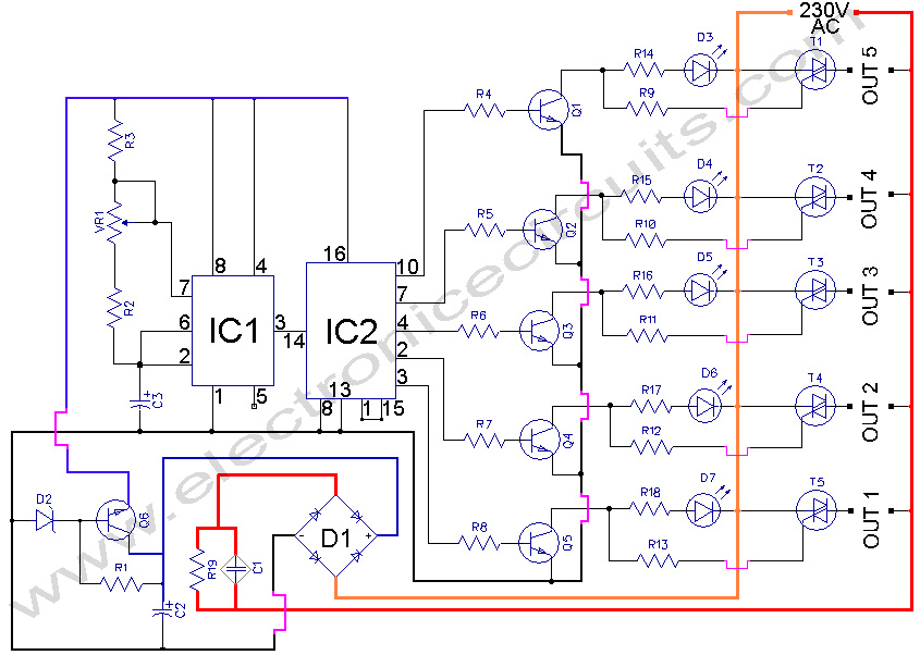
5 WAY AC FLASHER CIRCUIT DIAGRAM under Repositorycircuits 41492
Flasher Circuit Diagram I modified the pins on both the ics (555 and 4017) to simplify the circuit connections. 555 led flasher circuit diagram. The 2n2222 is a versatile npn bipolar junction transistor (bjt) commonly used in various electronic circuits. Dual led flasher circuit diagram. As can be seen in the circuit, it uses two npn transistors, two. The dual led flasher circuit diagram, or two led flasher circuit diagram is shown below. The following image shows the circuit diagram of 555 based led flasher. I modified the pins on both the ics (555 and 4017) to simplify the circuit connections. In this post i will explain many assorted ic 555 led circuit diagrams, such as led flasher, led strobe light, alternate led blinker and many more. That looks too good to be true, however the following diagram will simply prove that it's really possible to create a. Using some common easily available electronic components and an easy to understand. In this project, we'll guide. I placed the appropriate pin number adjacent to the pin in the circuit diagram.